
Originally published on December 10, 2013
In order to troubleshoot the components of a heat pump system, you must first understand them. Since much of North America has transitioned into the heating season, it’s perfect timing to review a component commonly found in residential heat pump systems: the suction accumulator.
What is a suction accumulator?
Suction accumulators are critical components of air-to-air and air-to-water heat pump systems.
What does a suction accumulator do?
Air-source heat pumps must maintain a delicate balance and proper control of liquid refrigerant under low ambient heating conditions to adequately provide cooling to the compressor, and avoid excessive refrigerant floodback. If liquid refrigerant is allowed to flood through the system and return to the compressor without being evaporated, it can cause damage to the compressor. Depending on the type of compressor, this damage could range from liquid slugging, loss of oil (in the compressor), or bearing washout.
To protect against floodbacks on systems vulnerable to liquid refrigerant damage such as heat pumps, the accumulator’s function is to intercept the liquid refrigerant before it can reach the compressor. When a coil defrost is required, the compressor is exposed to sudden surges of liquid that can create extreme stresses in the system. The accumulator can act as a receiver during the heating and defrost cycles when system imbalance or an overcharge from field service could result in excessive liquid refrigerant in the system.
The accumulator can store the refrigerant until needed and feed it back to the compressor at an acceptable rate. Major movements of refrigerant take place at the initiation and termination of a defrost cycle, and while it is not necessary or even desirable to stop this movement, it is essential that the rate at which the liquid refrigerant is fed back to the compressor be controlled. Along with this proper metering, the accumulator can effectively maintain the crankcase or bottom shell temperature at acceptable limits. A properly designed suction accumulator can provide excellent protection against both potential hazards and an increase in heat pump efficiency.
What type or size of accumulator should be used?
This component should be located in the compressor suction line between the evaporator and the compressor. It needs to have a volume/capacity large enough to hold the maximum amount of liquid that might return to it, and must have provisions for a positive return of oil to the compressor.
The actual refrigerant holding capacity needed for a given accumulator is governed by the requirements of the particular application, and the accumulator should be selected to hold the maximum liquid floodback anticipated. Typical accumulators manufactured for air conditioning or commercial usage have oil return orifices in size from .0625 to .125 inch diameter. The smaller orifice undoubtedly is more vulnerable to restriction from solder particles or other foreign material in the system, and an inlet screen would be advisable, particularly on systems with field-installed piping. Care should also be taken to prevent solder and flux from entering the accumulator, since excessive foreign material could plug the metering orifice, effectively trapping the compressor oil in the accumulator.
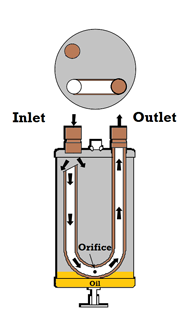 Note the refrigerant inlet is offset from the top of the J tube. As the refrigerant and oil enter the vessel, velocity separation takes place and the refrigerant expands due to the ambient temperature providing a heat source. At this point, the oil entering, (along with any liquid refrigerant) separates from the vapor refrigerant and falls to the bottom. The vapor refrigerant moves through the “J” tube as the compressor causes a pressure difference on between the inlet and outlet of the accumulator. As the refrigerant travels through the “J” tube, this causes a Venturi effect to take place across the orifice, drawing in oil from the bottom of the vessel. The vapor refrigerant carries the oil back to the compressor at a controlled rate.
Read Next: The Contractor’s Guide to Repairing or Replacing Flood-Damaged HVAC Systems