Step-by-step guide on how to replace the pleated filter media used in a residential air conditioning systems.
How to Change Your Pleated Air Filter
Reply
Step-by-step guide on how to replace the pleated filter media used in a residential air conditioning systems.
What’s the Difference Between a Ducted and Ductless Air Conditioning System?
Air conditioners provide cool air through two forms of delivery: ducted or ductless systems. The majority of homes in the U.S. are built with air ducts made from sheet metal that run from the main air conditioning unit to each room in the house. The ducts are hidden in walls and air is delivered to each room through vents. In ductless systems, the refrigerant from the outdoor condensing unit is sent directly to an air handler located on the wall or ceiling of a particular room.
While a ductless system can have several benefits, many homeowners with existing ductwork will be better off from a financial and comfort perspective by using a ducted system.
Benefits of Ductless Air Conditioning System
Concerns with Ductless Air Conditioning System
When to Consider Installing a Ductless Air Conditioning System
While we don’t recommend a ductless system for most homes, there are several situations where a ductless system should be considered over a traditional ducted one. These include:
The bottom line on Ductless Air Conditioning Systems
Your comfort, humidity and long-term reliability should all be factors in making a smart decision. As with any important HVAC question, it makes sense to talk with a professional. Contact a reputable licensed contractor who can explain the many options and variables when it comes to selecting the best solutions for your needs.
If you’re considering a ductless system, comment below and tell us some of the reasons it appeals to you!
For more information on ductless systems, click here.
The AC & Heating Connect staff did some research on the facts about ductless mini-split systems that might be of interest to contractors and distributors as they plan for the future growth of this segment.
Ductless Mini-Split System Sales Have Declined
While the ductless segment has posted impressive growth rates in the U.S. since 2005, the growth rates have been slowing recently and the largest ductless segment (small, single evaporator systems) have not grown at all since 2010. These sales remain stable at about 260,000 units per year, or only about 4% of total unitary AC shipments. Some larger VRF-style commercial systems continue to grow at higher rates, but their numbers in the U.S. remain small at only 28,000 units per year. There also appears to be some densely populated urban areas, which are growing faster than the overall segment.
Ductless Mini-Splits Are Not Efficient For Whole Home Retrofits
It is important to remember that ductless mini-splits are probably not ideal whole-home HVAC solutions in the U.S. due to the economics, which favor ducted replacements. The installed costs associated with using mini-splits to cool and heat an average 2,000 square foot home or business with ductless mini-splits would cost almost three times the cost of simply replacing a central AC system with another ducted system. Even in a space where you had to provide new ductwork for the central system, you could still expect to spend about 50% less on a typical central AC system installation versus the more expensive ductless options.
Possible Energy Loss From Ductless Mini-Split System
If you are considering a ductless mini-split which uses a lot of long exterior refrigerant line sets you should be careful to account for the potential energy losses from those lines. Even if properly insulated, lines running to second floor evaporators with significant exposure to the sun will like have losses and lead to underperformance during peak demand if not sized properly.
Comfort Concerns When Using a Ductless Mini-Split System
It is important to discuss the unique features of a ductless cooling system with your customers since these systems are common in the U.S. and are not well understood by many U.S. consumers. The typical comfort experience with mini-split systems could provide a real challenge for American consumers who are used to central AC systems with good airflow exchange, filtration and humidity control. Cold and hot spots are also common with ductless systems due to the spacing of the indoor units.
For more information on ductless mini-split systems, click here.
There are many types of specialized HVAC technology used in commercial buildings and these are often much different from those terms used in common residential applications. We thought it would be helpful to provide a summary list of the various types of commercial air conditioning systems used in the US today. Reviewing this list prior to or during conversations with your HVAC contractor might allow you to be more informed and less confused about the solutions being proposed for your commercial air conditioning needs.
Air Filter
A device used to remove solid, particles from the air stream. Air filters are typically located on the return side of the fan and upstream of any cooling/heating coils, ASHRAE recommends a minimum MERV rating of 6 or higher.
ANSI/AHRI Standard 340/360
This is the standard for performance rating of unitary air conditioning and heat pump systems from 65,000 to 250,000 Btu/hr.
Approach
For cooling towers, the approach is the difference between the leaving cooling tower water temperature and the ambient air wet bulb temperature. For chillers, the approach is the difference between the leaving chilled water temperature and the evaporating temperature of the refrigerant.
ASHRAE Standard 55
Thermal Environmental Conditions for Human Occupancy Standard; ASHRAE 55 is intended to provide comfort and sustainability.
ASHRAE Standard 62.1
Ventilation for Acceptable Indoor Air Quality Standard; Compliance with ASHRAE 62.1 indicates that the building meets the minimum ventilation requirements set forth by ASHRAE Standard 62.1.
ASHRAE 90.1 Compliant
With respect to unitary cooling equipment, compliance with ASHRAE 90.1 indicates the equipment meets the minimum efficiency requirements set forth by ASHRAE Standard 90.1.
ASHRAE Comfort Zone
This is the range of indoor temperature and humidity conditions for summer and winter conditions that have been found to be acceptable by 80% of the surveyed occupants.
Barometric Relief Damper
This is a damper that allows excess air to exit the building to prevent over pressurization of the building.
Blower
Typically a centrifugal type fan inside of a housing, a blower is capable of delivering air flow at a higher pressure versus a fan.
Blower Proving Switch
A switch that provides confirmation that the blower is running.
Compressor
This is the heart of the system, a machine that is used to compressor refrigerant gas. Compressor types include scroll, reciprocating, rotary, screw, and centrifugal.
Commissioning
Testing the installed HVAC system to ensure it complies with building requirements, codes, manufacturer’s specifications, and performance data. At the completion of the commissioning process the commissioning agent will issue a report documenting the results of the commissioning process.
Condenser Coil
A condenser coil is a heat transfer coil that condenses refrigerant and rejects heat from the system. The condenser coil is typically air or water cooled and is sized to reject the heat absorbed by the evaporator plus the heat of compression.
Condenser Fan Motor
A motor that is used to drive a fan/propeller to move air through an air cooled condenser.
Cooling Load
This is the total heat load that must be removed from the conditioned space per unit time.
Cooling Coil
A cooling coil is the heat transfer coil in which the refrigerant boils and heat transfer takes place. The cooling coil lowers the temperature of the air as it travels through the coil.
Cooling Degree Day
Used to estimate the energy required for air conditioning, a cooling degree day is approximately equal to the mean daily temperature less the base temperature.
Constant Air Volume (CAV)
A type of system that delivers a constant air flow quantity at a variable supply air temperature. Most residential systems are CAV systems.
Crankcase Heater
Helps prevent refrigerant migration to the compressor during the off cycle.
Damper
Typically used in zoning applications, a damper is a moveable plate installed in the ductwork used to direct or regulate air flow.
DDC
Direct digital control, control of HVAC processes and equipment via microprocessors.
Demand Control Ventilation
A ventilation strategy that introduces ventilation air based on CO2 levels in the occupied zone. The purpose of demand control ventilation is to provide the correct amount of ventilation air and to avoid costly over ventilation.
Discharge Air Heating Reset
A method of controlling coil leaving air temperature during heating based on the outdoor temperature.
DOE
Department of Energy; a federal agency that is responsible for setting HVAC minimum equipment efficiency standards.
Economizer
Used to reduce the mechanical cooling load, an economizer allows the use of outside ventilation air for supply air when the enthalpy or temperature of the outdoor air is lower than required supply air during the cooling cycle.
EER
Energy efficiency ratio; equal to Btu/hr ÷ Watts.
Energy Recover Wheel
May be referred to as heat wheel, used to recover sensible and latent energy from exhaust air.
Energy Star®
Applied to unitary equipment 20 tons or less, Energy Star® labeled equipment exceeds EPA guidelines for energy efficiency.
Exhaust Air
Removes air from inside the building to outside the building. Generally used for removing odors or for proper building pressurization.
External Static Pressure
Pressure that the fan must overcome due to losses after the fan or unit. Typical external static pressure loses include ducts, fittings, registers and diffusers. External Static Pressure does not include the pressure loss of the fan or unit.
Freezestat
A thermostat located on the evaporator coil that protects the coil from damaging ice build-up.
Full Load
The maximum load that a piece of equipment can handle.
High Efficiency
Term used to indicate that the equipment is more energy efficient than average.
High Pressure Switch
A switch that protects the compressor and system from abnormally high discharge pressure conditions.
Hot Gas Bypass
Used to control the capacity of the system at low loads, hot refrigerant gas is bypassed to the low side of the system to better match evaporator capacity to the load.
Humidifier
A device that introduces moisture into the air stream for humidification purposes.
Humidistat
A humidity sensor that is used to control heating and cooling equipment to maintain desired humidity levels.
IECC
International Energy Conservation Code; IECC is a code that establishes minimum design and construction requirements for energy efficiency.
IEER
Integrated Energy Efficiency Ratio; expresses cooling, weighted part load EER for commercial unitary air conditioning and heat pump equipment at different loads.
IPLV
Integrated Part Load Value; the efficiency performance factor at part load cooling. This performance factor is weighted towards operating hours at part load.
Latent Load
Load due to moisture introduced into a building. Latent loads may come from ventilation air, people, equipment and infiltration. Latent loads are a concern for cooling and humidifying applications.
LEED
Leadership in Energy and Environmental Design; sponsored by the U.S. Green Building Council (USGBC), LEED is a certification program that guides the design, construction, operation and maintenance of buildings and homes.
Life Cycle Cost Analysis
Assesses the total cost of ownership. It includes material cost, installation cost, operating expenses, maintenance expenses and often replacement expenses. A life cycle cost analysis can be used to determine if a new or a high efficient system should be purchased.
Load Calculation
A detailed calculation of the heat loss/gain for the building that is used to size the heating and cooling equipment. Load calculations for commercial buildings are typically performed using software that takes into account historical weather data.
Low Pressure Switch
A switch that protects the compressor and system from abnormally low suction pressure conditions.
Make Up Air
Outside air introduced to the space to prevent negative building pressures and to provide ventilation air.
MCA
Minimum circuit ampacity; this is the minimum ampacity for the circuit supplying the equipment.
Mixed Air
Return air from the space and outside air mixed together.
MERV
Developed by ASHRAE as a rating system for filters, Minimum Efficiency Reporting Value rates filter performance on a scale of 1 to 16. The higher the MERV value the more efficient the filter is at trapping airborne particles.
Part Load
A load on a piece of equipment that is less than its maximum capacity. Most HVAC equipment operates the majority of time at part load.
Pay Back Analysis
This determines the period of time that is required for the investment to repay the initial investment. Includes factors such as: initial cost, maintenance cost and savings.
Programmable Thermostat
A thermostat that his capable of keeping different cooling and heating schedules, based on building usage, for efficiency and comfort purposes.
Reheat
Heating air that has previously been conditioned. Often used to dehumidify air or to provide extra heating capacity.
Reheat Coil
Typically located downstream of the cooling coil in dehumidification applications, the reheat coil increases the temperature of the air after it passes through the coiling coil. This is a sensible heating operation.
Return Air
Air returned to an air handling unit from the conditioned space.
Roof Curb
Roof support structures for equipment to be placed on.
SEER
Seasonal Energy Efficiency Ratio; The SEER rating is the cooling output divided by the total electric energy input during a typical cooling season.
Sensible Load
The load required to keep the temperature in the space constant. Sensible loads can come from ventilation, infiltration, people and interior loads such as lights and electronics.
Smoke Detector
This is a device that detects smoke. Often installed in a space or in the return air path of an air handling unit.
Standard Efficiency
Term used to indicate that the equipment has average efficiency.
Supply Air
Air provided to condition a space.
Thermal Expansion Valve
A valve that meters the flow of refrigerant to the evaporator coil. The flow is metered based on superheat leaving the evaporator coil.
Thermidistat
A temperature and humidity sensor that is used to control heating and cooling equipment to maintain desired temperature and humidity levels.
Total Static Pressure
Pressure that the fan must overcome due to pressure losses of the entire system. Typical pressure loses includes coils, filters, fan, ducts, fittings, registers and diffusers. External Static Pressure does not include the pressure loss of the fan or unit.
Variable Air Volume
A type of system that delivers a variable air flow quantity at a variable supply air temperature.
Ventilator
Mechanical equipment that has the ability to supply the space with ventilation air.
VOC
Volatile Organic Compound; emitted gases from solids or liquids. VOCs in a space is often reduced by supplying the space with ventilation air or by filtering the return air with a high performing filter.
I can remember when I first started in the HVACR industry; there were only 3 colors of refrigerant bottles in the back of the truck – green, purple and white. Along with these limited color options, I can remember using cardboard slide rules and calculators to determine charge amounts and system failure diagnosis. Fast forward to today, it seems the industry has run out of colors to select and represent all the different flavors of refrigerant. With each new eco-efficient refrigerant, several replacements have appeared and in turn, new colors. Along with these changes, out went the cardboard tip cards/calculators, in came the mobile apps.
An app is a shortened slang term for an “application”. These are small software programs that can be used on a variety of different device platforms. Several HVACR manufacturers, along with industry associations have developed apps for computers, smart phones and tablets. Mobile apps started becoming popular just a few short years ago, but their growth has increased exponentially since 2009. Today there are millions of apps for basically every aspect of our lives, including the skilled trade industry.
Applying Mobile Apps for the HVACR Industry:
In my mind, the useful apps developed for the skilled trades fall into one of two categories, Product related or Industry related apps.
Product related apps are developed to provide instant mobile help on a particular OEM’s device or component. Product apps are designed to replace the printed technical literature scattered throughout the service office or truck. This direct access to product knowledge looks to enhances the contractor’s experience by reducing the research time and providing the most up to date information available.
Industry related apps refer to the cardboard calculators I mentioned earlier. These apps are designed to replace the previous generation of static printed calculators with better interfaces, content, and easily updated calculations. I see these more as tools, used in conjunction with a system like you would a screw driver or wrench. These apps allow for increased accuracy in the servicing and troubleshooting of the system.
Most HVACR manufacturers have developed mobile apps to make information easily available at the contractor’s jobsite. Emerson Climate Technologies™ “Mobile Toolbox” of mobile apps is designed to help contractors find solutions to common issues in the field quickly and easily. Related to the Product category, apps such as Emerson X-Check™, Copeland X-Ref™, and White-Rodgers Mobile™ focus on finding replacement parts and technical product information. “HVACR Fault Finder” focuses on understanding the compressor electronic module line, along with allowing contractors to input the diagnostic code for help with compressor troubleshooting.
In the Industry related category, Emerson PT Pro™ and HVAC Check & Charge™ are technical resources. Emerson PT Pro is a quick refrigerant pressure/temperature app designed to replace those worn out multi-fold micro charts supplied to the industry for years. It offers information on over 20 different refrigerants, along with adjustment for high altitude applications. The HVAC Check & Charge app allows for a quick calculation for adjusting initial A/C system refrigerant charge. This system charge calculation is based on the cardboard superheat slide rulers used for years. Since the emergence of “dry-charge” units, these calculations have a renewed interest, now more than ever.
Top Ten Apps For Skilled Trades:
http://www.itbusiness.ca/slideshows/10-handy-android-apps-for-the-skilled-trades
HVAC Apps for Homeowners:
While HVAC manufacturers often design mobile apps with contractors in mind, some have also produced apps for consumers. An example is the Emerson e-Saver™ app. This app helps contractors and homeowners understand unit replacements respective to their current system. This app allow for users to better understand the true cost of operation in different locations and how those units would match up against optional replacement systems. This app also includes a custom report for homeowners to reference these replacement options.
Emerson Climate Technologies’ website offers HVAC mobile apps content that explains each of the apps, as well as offers links for easy download. All of the apps can be downloaded for free through their respective app stores for the Apple and Android platforms, and a few of the apps are also available for the Blackberry platform.
This is part 2 of a 3 part series on understanding compressor replacements.
What are compression ratios and how do they affect compressors?
As discussed in the first part of this series, an air conditioning compressor’s re-expansion gas directly affects its volumetric efficiency at different system operating conditions. The volumetric efficiency of a reciprocating (piston) compressor can vary over a wide range, depending on the compressor design and the compression ratio.
Compression Ratio
The compression ratio is the ratio of the absolute discharge pressure (psia) to absolute suction pressure (psia), found using the formula Discharge Pressure Absolute ÷ Suction Pressure Absolute.
In that chart that accompanies part one of this series, the left side (Y-axis) represents compression ratios. As the compression ratio increases, the volumetric efficiency decreases in reciprocating compressors.
To convert any gauge pressure to absolute, add 14.7 (or 15 to make it easy) to the pressure reading from a manifold gauge set. 14.7 represents the atmospheric pressure that the manifold gauge already takes into consideration. (At 0 psig, the actual reading is 14.7 psia.)
Consider a few examples:
Discharge = 185 psig + 15 = 200 psia
Suction = 5 psig + 15 = 20 psia
This example uses a low temperature application range, and rounds the 14.7 (atmospheric) to 15. Using these psia pressures from the examples above, a 10:1 compression ratio is calculated
200 psia = 10:1
20 psia
10:1 is a compression ratio commonly found in refrigeration applications. If you are thinking about air conditioning, it is often around 3:1 or 4:1
Example 2:
200 psia = 20:1
10 psia
In this example, the suction pressure drops by 10 psia, which doubles the compression ratio. At this compression ratio, a compressor designed for a 10:1 ratio would have a tough time surviving. Do you think the Service Tech would notice this drop in absolute suction pressure? Probably not.
Example 3:
400 psia = 20:1
20 psia
In this calculation, absolute discharge pressure is raised to 400 psia, essentially doubling it, to give the same 20:1 compression ratio. Do you think the Service Tech would notice if his discharge pressure doubled? Hopefully. In either case, the compressor would have a difficult time operating at double its rated compression ratio. After understanding how compression ratio affects volumetric efficiency, at what efficiency level do you think this system is currently operating at, versus its design envelope?
It is important to pay attention to those system pressures, and in the next article we will tie compression ratio and volumetric efficiency together for a better understanding of service compressor replacements.
Part 1 – Compressor Volumetric Efficiency for HVAC Systems
Part 3 – Service Compressor Replacements
This is part 1 of a 3 part series on understanding service compressor replacements.
What is re-expansion gas and how does it affect compressors?
It is important for contractors to understand why compressor capacities change at different system conditions and know what steps to take when servicing or replacing compressors. There are several types of mechanical compression used around the world in air conditioning applications available today: rotary, screw, reciprocating and scroll, just to name a few. The focus in this series will be on reciprocating (piston) compression and how this style of mechanical compression relates to scroll compression.
Volumetric Efficiency:
Simply defined, volumetric efficiency is the ratio of the amount of refrigerant gas entering the compressor (suction) versus the amount of gas leaving the compressor (discharge). For example, if the compression cycle is 100% efficient, it means that all of the gas coming into the compressor’s suction fitting is traveling through the system and leaving the compressor’s discharge fitting. Volumetric efficiency is typically expressed as a percent, using the formula volume pumped divided by displacement.
Because of the limitations on clearances in reciprocating compressors, (the area between the top of the piston and bottom of the valve plate) there is always a small amount of re-expansion gas left behind in the cylinder. Even at top center of the discharge stroke, a small amount of gas still remains. This gas occupies the space between the top of the piston/valve plate and in most cases, the discharge port(s) must re-expand upon returning to the suction stroke of the compression process. This volume of gas (clearance volume) reduces the overall volumetric efficiency incrementally as it grows.
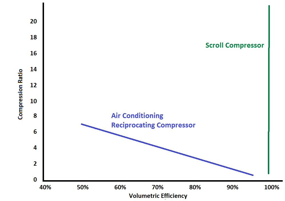
Scroll compressors are more efficient because they don’t use pistons, reeds, or valves. When the first pocket of the scroll set closes and captures a volume of refrigerant, all of it is swept along in the compression process and discharged out of the scroll members to the system. Unlike piston compressors, there is no clearance area or clearance volume to create losses; thus, scroll compressors are theoretically considered 100% efficient.
The chart below may provide a clearer picture. The bottom of this chart (X axis) represents the “volumetric efficiency”—expressed on the chart as a percent. Within the X and Y axis of the chart, the green line represents a scroll compressor’s efficiency, while the blue line represents a reciprocating (piston) compressor. The left side of the chart (Y Axis) expresses the compression ratio (absolute discharge divided by absolute suction).
In the next installment, we’ll discuss compression ratio as we continue our journey to better understanding proper service compressor replacements.
In 1987, an international treaty called the “Montreal Protocol” was established to protect the atmospheric ozone layer from the harmful effects of certain manufactured chemicals. Now, over 25 years later, we are in the midst of the forced phase out of R-22 (an HCFC), one of the restricted chemicals commonly used as an air conditioning refrigerant. The transition of the U.S. air conditioning industry from R-22 to R-410A has actually been going on for about ten years as the first R-410A systems were introduced in the mid 1990’s. We are now in the final stages of this transition, which includes the painful effects of shortages and high prices for replacement refrigerant, and confusion over various retrofit application challenges. As our industry completes this transition it is important to know there might be another refrigerant change on the horizon and we might not get 25 years to get ready for it like we did with the last one.
The next refrigerant transition we are anticipating will be driven by government regulating authorities’ desire to address concerns about “global climate change” or “global warming”. While R-410A is better for atmospheric ozone, scientists have determined that lower global warming potential (GWP) refrigerants are desirable to address potential long term climate impact. So, the industry is busy working on several new refrigerants with lower global warming potential in advance of anticipated regulations in this area. This article will provide some background information on how this is progressing and what you might expect to see over the next few years.
Here are four things to keep in mind as you hear about these possible new refrigerant transitions and conversions.
As the U.S. HVAC industry has done in the past, many companies are actively supporting AHRI’s AREP (Alternative Refrigerants Evaluation Program) investigations into the several alternative refrigerants. Emerson is also working with industry groups like AHRI, NATE, ASHRAE and ACCA who also facilitate the flow of industry information. We are working directly with the chemical manufacturers, our OEM customers and large groups of contractors, to make sure we are ready with compressors to support any direction the industry decides to go. Emerson is currently considering several viable low GWP refrigerants and we are not actively promoting any one refrigerant path for U.S. air conditioning at this time.
The following are some links to recent articles on this subject which might be of interest.
Contracting Business, February 11, 2013
On a Quest to Reduce Refrigerant Leaks
ACR News, December 6, 2012
Linking low GWP refrigerants to energy policy may be counter-productive
New York Times, November 22, 2012
Effort to Curb Coolant Falters, Sometimes at Home
Reuters, November 7, 2012
One aspect of a home or business’ heating and cooling system that is often overlooked is the electrical usage monitoring system, most commonly seen through meters installed outside a home or facility. Smart meters have increased in popularity over the last few years as a way to help control energy usage, provide valuable feedback for end users and utility companies, and ultimately encourage people to take a more vested interest in the efficient operation of their HVAC systems. Emerson Climate Technologies is proud to sponsor an editorial series with TriplePundit.com to explore a variety of HVAC-related issues and this article titled “What is a Smart Meter?” provides an overview of why homeowners and businesses should care about keeping an eye on their energy usage through smarter devices.
http://www.triplepundit.com/2013/02/what-is-a-smart-meter/