Guide to Thermostatic Expansion Valves

Learn how thermostatic expansion valves work in HVAC systems.

Originally published on June 24, 2013

Understanding TXVs

Since the minimum efficiency regulation changed to 13 SEER in January 2006, most OEM systems now incorporate a thermostatic expansion valve (TXV) style metering device as the standard for air conditioning systems. It is now extremely important for the HVAC technician to understand the design and operation of this type of valve.

The thermostatic expansion valve (TXV) is a precision device, which is designed to regulate the rate at which liquid refrigerant flows into the evaporator. This controlled flow is necessary to maximize the efficiency of the evaporator while preventing excess liquid refrigerant from returning to the compressor (floodback).

One of the design features of the TXV is to separate the high pressure and low pressure sides of an air conditioning system. Liquid refrigerant enters the valve under high pressure via the system’s liquid line, but its pressure is reduced when the TXV limits the amount of this liquid refrigerant entering the evaporator.

Understanding the Function of the TXV

The thermostatic expansion valve controls one thing only:  the rate of flow of liquid refrigerant into the evaporator. Contrary to what you may have heard, the TXV is not designed to control:

  • Air Temperature
  • Head Pressure
  • Capacity
  • Suction Pressure
  • Humidity

Trying to use the TXV to control any of these system variables will lead to poor system performance – and possible compressor failure.

Understanding How the TXV Controls the System

As the thermostatic expansion valve regulates the rate at which liquid refrigerant flows into the evaporator, it maintains a proper supply of refrigerant by matching this flow rate against how quickly the refrigerant evaporates (boils off) in the evaporator coil. To do this, the TXV responds to two variables: the temperature of the refrigerant vapor as it leaves the evaporator (P1) and the pressure in the evaporator itself (P2). It does this by using a movable valve pin against the spring pressure (P3) to precisely control the flow of liquid refrigerant into the evaporator (P4):

TXV Pressure Balance Equation
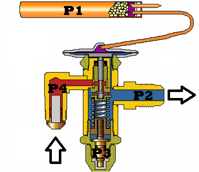
TXV
P1+P4 = P2+P3
P1 = Bulb Pressure (Opening Force)
P2 = Evaporator Pressure (Closing Force)
P3 = Superheat Spring Pressure (Closing Force)
P4 = Liquid Pressure (Opening Force)


Understanding How the TXV Transfers Energy

Here is a closer view of the TXV in operation. The valve pin restricts the flow of the liquid refrigerant. As the flow is restricted, several things happen:

  • The pressure on the liquid refrigerant drops
  • A small amount of the liquid refrigerant is converted to gas, in response to the drop in pressure
  • This “flash gas” represents a high degree of energy transfer, as the sensible heat of the refrigerant is converted to latent heat
  • The low-pressure liquid and vapor combination moves into the evaporator, where the rest of the liquid refrigerant “boils off” into its gaseous state as it absorbs heat from its surroundings.

The pressure drop that occurs in the thermostatic expansion valve is critical to the operation of the refrigeration system. As it moves through the evaporator, the low pressure liquid and gas combination continues to vaporize, absorbing heat from the system load. In order for the system to operate properly, the TXV must precisely control the flow of liquid refrigerant, in response to system conditions.

Share
print

Was this helpful?

Vote This Post Up 13,609Loading...

270 thoughts on “Guide to Thermostatic Expansion Valves

  1. I have an AC unit that shuts itself off before reaching the set temperature in the home (set at 73 degrees – only reaching 79-80). I have had the compressor replaced, coils cleaned, thermostat replaced, and even the control board in the actual furnace unit replaced. I had another company come out to go over the whole system, which they said was fine but they thought it might be the TXV line which was dripping – quoting me $542 to replace the line. Could the TXV line been responsible for the whole system shutting off?

    • Based on the information you provided, it sounds like your system was shutting down on the compressor internal overload protection, before meeting the setpoint temperature. If the dripping from the TXV line is oil, then this is a good indication that the system might have a leak, and may have lost some of the refrigerant charge. In general, if the system has lost charge and is tripping on overload protection, it is starting to enter a “loss of charge” failure mode. This event could be what is causing your whole system to shut off. My advice would be to get a clear understanding of the work being suggested to your system, and be sure to explain the system history and past experiences with a Certified Contractor.

      Hope this helps,
      Scott

  2. I am a service tech at the HVAC company I work for. I have to go back to school once more for my refrigeration apprenticeship.
    What I would like to know is in relation to improper positioning of the Bulb. A couple of our installers were not properly shown how to position the bulb other than to make sure it is on top if the line is horizontal. In school they taught us to ensure that the cap tube coming off the bulb is positioned to ensure only refrigerant vapour will be used as the opening force.
    Now these installers have installed quite a few of these bulbs upside down and if my understanding is correct then the diaphragm is always getting liquid pressure from the bulb and being forced open. I have had to replace 3 TXV so far since even after repositioning them I can not get proper superheat.
    So finally the question, does having the bulb positioned this way end up breaking the TXV? Or is it just that these just happen to be bad TXV? I am leaning towards it being the cause of the failure, however I can’t find any documentation to back that up.
    Thank you for your time.

    • Jeese,

      The best place to mount the bulb is on a horizontal run of the suction line. You are correct that the preferred location for suction lines less than 7/8″ tube is at the 12 o’clock position. The preferred location for suction lines greater than 7/8″ tube is at the 8 or 4 o’clock position. The reasoning for location on the larger size tube is that this location is close enough to the bottom of the pipe to detect any liquid refrigerant but far enough off the bottom so as not to be effected by any oil laying on the bottom of the tube.

      In some cases it is not possible to clamp the valve to a horizontal run of pipe. The conventional wisdom use to be that if the bulb was mounted in the vertical position with the capillary tube at the 6 o’clock potion, that the charge in the bulb would drain out of the bulb and into the powerhead leaving the valve unable to sense the suction line temperature causing the valve not to perform properly. However, as long as the bulb is colder than the powerhead the charge will not migrate and will stay in the bulb regardless of the bulb orientation. In addition, bulb orientation will not impact the reliability or life expectancy of the valve.

      Regardless of the position of the bulb it should be clamped securely to the tube and well insulated. The insulation should be wrapped completely around the bulb and the section of tube that the bulb is clamped to. The purpose of the insulation is to insure that the bulb senses the pipe temperature and is not influenced by any other temperatures.

      Thanks, and I hope this helps,
      Scott

  3. What would cause a TX valve to go bad? What is the normal time and cost of a repair? My AC unit is only 4 years old and it seems to me that the TX valve should have lasted longer. Is this something that I am going to have to fix every 4 years?

    • There are several primary causes for a TXV failure. One possibility is debris within the system traveling downstream and restricting refrigerant flow at the valve port. Another common failure mode is damage to the remote sensing bulb or capillary tube caused by system vibration. Both of these failures will starve the evaporator and increase system superheat.

      As for the expected useful, system components like TXV’s are designed to an OEM specification for useful life expectancy so these should be the same as for the whole system and the other components.

      As for the costs to change out a TXV, these costs range from system to system and from contractor to contractor. We usually suggest securing several competitive bids from reputable contractors also and getting a second, independent opinion on recurring problems.

  4. We installed MOP TXV as desuperheating valve and sub-cooler/economizer in the 2nd stage of compressor and mistakenly bent 1/4in copper tube w/c was causing restricted/reduced pressure in the equalizer. The liquid line coming from sub-cooler was still warm resulted to high head pressure. When we corrected its equalizer pipeline, upon testing the unit the liquid line become wet in less than 20 minutes.

    If P1+P4 = P2+P3 (opening force = closing force), why refrigerant flow was restricted resulted to high head pressure and inefficient subcooling if P2 was lost?

    Thank you very much.

    • The equalizer line senses the suction pressure at the outlet of the evaporator while the TXV bulb senses the temperature at the same point. As a result, the valve “knows” what the superheat is and can open/close to maintain a relatively constant superheat. But, if there is a restriction in the equalizer line, then the pressure sensed at the valve side of the restriction will be higher than the pressure downstream of the restriction. This higher pressure will tend to make the TXV “close” resulting in an increase in superheat.

      The P2 pressure you refer to is not “lost”. It is in fact higher than it should be, resulting in an imbalance in the closing direction.

      The severity of the restriction also needs to be considered. If it is just a minor restriction than as the suction pressure drops, you may see a small delta P across the restriction causing some increase in superheat. But when the system is operating with stable suction pressures, then the valve should operate normally.

      If this is a Balance Ported valve, then it is also possible that you have a leak across the internal seal allowing liquid refrigerant into the equalizer area. This too will cause in increase in pressure at the underside of the diaphragm (P2) causing the valve to move in a closing direction.

      In summary then, any restriction in the equalizer line will result in higher superheat and that is why your sub-cooler is not operating at its design condition.

      Hope this helps,
      Scott

  5. Thank you for your information. I have a question which i am not sure of if u can help.

    when fitted into a refrigeration system the TEV operates by
    a. variations in refrigeration flow due to superheat control
    b. the system pressure being greater than spring pressure
    c. reacting to flow measurement
    d. reacting to changes in the liquid line durring operation

  6. All metering devices have a rated capacity range. This capacity rating is based back on the device receiving 100% liquid refrigerant to the valve, (at least 1°F Subcooling). Any “vapor” refrigerant passing through the valve, de-rates the valve’s capacity and thus reduces the rated capacity of the metering device.

    If the load on the Evaporator requires the metering device to operate at 100%, and due to “vapor” the valve cannot supply enough liquid refrigerant to the evaporator coil, this could cause an increase in system Superheat and damage to the refrigerant cooled Compressor.

  7. HI dear
    if the flow to expansion valve have some gas what effect on valve performance?
    since we don’t have sub-cooling
    tanks

    • There will not be any effect on the valve…effect will with the evaporating coil..its cooling rate falls down due to entry of vapour refrigerant

        • Hi Shyam,

          A capillary tube style metering device acts much like a “fixed orifice”, as the refrigerant is metered by three parameters. The three parameters in which the refrigerant is metered are, internal dimension (ID) of the capillary tube, length of the capillary tube, and differential pressure between the tube inlet and outlet. Capillary tubes cannot respond to any changes in system load and evaporator superheat, unlike a TXV/TEV.

          Scott

        • Hi Al Oma,

          Generally I would say no, as the system needs a metering device and placing another metering device in parallel with the first could lead to problems. Not knowing how the “bypassed” valve will respond or how the valve fail (open/Closed) could cause a loss of control with the liquid refrigerant being fed into the evaporator. These metering devices control the expansion and evaporation of the refrigerant in the coil to provide cooling. If the liquid refrigerant does not vaporize before returning to the compressor, this could lead to a floodback scenario for the compressor.

          Hope this helps,
          Scott

    • Have a question,,, my home ac/ heat worked fine,,, heat pump,,,, everything was working fine one night and next day I found the connector on side of pump burnt off and all freon gone,, r410a,,,, ok bought new pump and installed and vaccumed and recharged and a min or few mins system line freezes up inside before expansion valve and on suction line before pump outside and what looks as the dryer freezes up also,,, coils r clean,, is this due to the expansion valve

      • Hi Tommy,

        It is very difficult to troubleshoot a system without actually being on the job site. But by your explanation, freezing of the liquid line after the dryer means there is a drop in pressure, causing a drop in temperature at that portion of the line. If the line (liquid line) freezes up at the dryer, then the dryer could be clogged and is acting as a metering device. After that point the entire system acts as the evaporator.

        Hope this helps,
        Scott

        • Hey man I have a problem my 6 yr old trane heat pump condensor with horizontal lef t airhandler they fliped the evap coil to make it drain correct but thesubcool is 10 degree and goes up when I add freon but the suction pressure stays at 38 degree inside coil temp I replaced txv 6 months ago and still doing the same thing

          • When the suction line on a A/C does not sweat, but the compressor runs and the amperage is okay, what could be the cause?

          • Hi Seymour,

            This could be normal operation as sweat or condensation will only form when humid air is in contact with a cold surface, in this case the suction line. A qualified service technician would use refrigerant service gauges that connect to the unit that read pressure and temperatures to determine correct operation.

Let us know your thoughts

Your email address will not be published. Required fields are marked *